Distribution by
Farnell
Farnell
Distribution by
Farnell
Farnell
Push button, Series 71, Ø 25 mm, non illuminative, Flush, 2 NC + 2 NO, Gold, IP65, PCB terminal
- 61-9841.2
- 71-611.0
- 61-9933.0
- 71-672.026


Add Accessories & Tools
Your product:
Product range
- HMI function:
- Push button
- Series:
- Series 71
Front
- Front dimension:
- Ø 25 mm
- Front form:
- Round
- Front bezel colour:
- Nature
- Front bezel material:
- Aluminium
Mounting
- Design:
- Flush
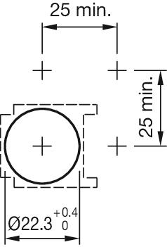
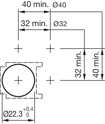
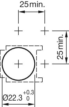
- Mounting cut-out:
- Ø 22.5 mm
- Mounting type:
- Panel mounting
Operating-/Indication part
- Lens colour:
- Red
- Lens material:
- Aluminium
- Lens illumination:
- Non illuminated
- Lens shape:
- Flush
- Lens optics:
- opaque
Electrical characteristics
- Switching voltage and switching current:
Switch rating AC cosφ 0,7 … 0,8
gemäss EN IEC 60947-5-1
Voltage
250 VAC
Current
3 A
Switch rating DC
gemäss EN IEC 60947-5-1
Voltage
24 VDC
250 VDC
Current
3 A
0.5 A
- Contacts configuration:
- 2 NC + 2 NO
- Switching rating:
- 250 V @ 3 A
Mechanical Characteristics
- Terminal:
- PCB terminal
- Contact material:
- Gold
- Switching action:
- Momentary
- Switching system:
- Snap-action switching element
- Switching positions:
- 3 positions
- Tightening torque:
- Fixing nut max. 0.5 Nm
- Total weight:
- 0.017 kg
Ambient Condition
- IP front protection:
- IP65
- Operating temperature:
- – 25 °C … + 55 °C
- Vibration resistance:
- Max. 100 m / s² from 10 Hz ... 500 Hz, (sinusoidal EN IEC 60068-2-6)
Other
- Housing colour:
- Black
- Housing material:
- Plastic, according to UL 94 V0
- Product attributes:
- Pitch of the front plate mounting holes must agree with the printed circuit board holes Ø 3.5 mm
- max. number of switching elements:
- 1
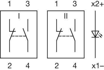
- Wiring diagrams:

Share and save this product
Download files
0 in stock Loading ...
Add to Cart
Your product consists of the following 4 COMPONENTS:

Front
- Front form:
- Round
Operating-/Indication part
- Lens colour:
- Red
- Lens material:
- Aluminium
- Lens illumination:
- Non illuminated
- Lens shape:
- Flush
- Lens optics:
- opaque
Mechanical Characteristics
- Weight:
- 0.002 kg
Certificate
- REACH:
- REACH compliant
- RoHS:
- RoHS compliant
Other
- Short Description:
- Lens, Ø 19.7 mm, Non illuminated, Red, Flush, Aluminium
- Dimension:
- Ø 19.7 mm
- Hints:
- The colour of anodised aluminium parts can vary due to technical production reasons
Download files
0 in stock Loading ...
Add to Cart

Mounting
- Mounting type:
- Panel mounting
Operating-/Indication part
- Lens illumination:
- Illuminated
Electrical characteristics
- Switching voltage and switching current:
Switch rating AC cosφ 0,7 … 0,8
gemäss EN IEC 60947-5-1
Voltage
250 VAC
Current
3 A
Switch rating DC
gemäss EN IEC 60947-5-1
Voltage
24 VDC
250 VDC
Current
3 A
0.5 A
- Surge voltage resistance:
- 2500 VAC, 50 Hz, 1 minute, as per DIN / IEC 60512-2 between all terminals and earth
- Recommended minimum operational data:
Voltage
5 VAC/DC
Current
10 mA
Mechanical Characteristics
- Switching action:
- Momentary
- Switching system:
- Self-cleaning, double-break snap action switching system, 1 normally closed and 1 normally open contact per element.
- Mechanical lifetime:
- 2 Mil. cycles of operation
- Operating force:
- 3 N ... 7 N
- Operating Travel:
- ca. 3 mm
- Tightening torque:
- Fixing nut max. 0.5 Nm
- Weight:
- 0.005 kg
Ambient Condition
- IP Protection:
- IP65 front side
- Operating temperature:
- – 25 °C … + 55 °C
- Storage temperature:
- – 40 °C … + 85 °C
- Shock resistance:
- Max. 500 m/s², pulse width, 3-axis (sinusoidal EN IEC 60068-2-27)
- Vibration resistance:
- Max. 100 m / s² from 10 Hz ... 500 Hz, (sinusoidal EN IEC 60068-2-6)
- Climate resistance:
- Damp heat, steady: 56 days, + 40 °C/93 % relative humidity, according to EN IEC 60068-2-78
Certificate
- Conformities:
- CE, UKCA, 2011 / 65 / EC (RoHS), 2014 / 35 / EU (LVD)
- REACH:
- REACH compliant
- RoHS:
- RoHS compliant
Other
- Short Description:
- Actuator, Illuminated, Momentary
- Housing colour:
- Black
- Housing material:
- Plastic, according to UL 94 V0
- Product attributes:
- Pitch of the front plate mounting holes must agree with the printed circuit board holes Ø 3.5 mm
- Hints:
- Pitch of the front plate mounting holes must agree with the printed circuit board holes Ø 3.5 mm
- Wiring diagrams:
- Mounting cut-outs:
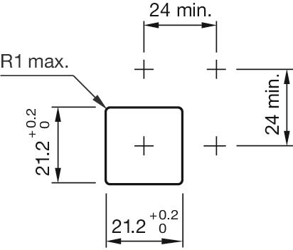
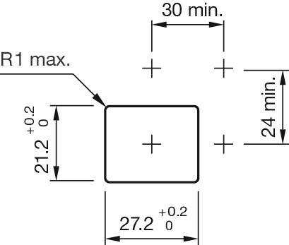
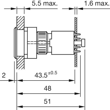
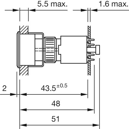
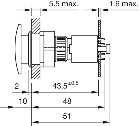
- Dimension drawings:
Download files
0 in stock Loading ...
Add to Cart

Front
- Front dimension:
- Ø 25 mm
- Front form:
- Round
- Front bezel colour:
- Nature
- Front bezel material:
- Aluminium
Mounting
- Mounting cut-out:
- Ø 22.5 mm
- Mounting type:
- Panel mounting
Mechanical Characteristics
- Weight:
- 0.005 kg
Certificate
- REACH:
- REACH compliant
- RoHS:
- RoHS compliant
Other
- Short Description:
- Front bezel set, Ø 25 mm, Ø 19,7 mm, Nature, Aluminium
- Dimension:
- Ø 25 mm
- Internal size:
- Ø 19,7 mm
- Product attributes:
- For indicator, push button, illuminated push button
- Hints:
- The colour of anodised aluminium parts can vary due to technical production reasons
- Mounting cut-outs:
Download files
0 in stock Loading ...
Add to Cart

Electrical characteristics
- Contacts:
- 2 NC / 2 NO
- Switching rating:
- 250 V @ 3 A
Mechanical Characteristics
- Terminal:
- PCB terminal
- Contact material:
- Gold
- Switching system:
- Snap-action switching element
- Switching positions:
- 3 positions
- Weight:
- 0.003 kg
Certificate
- REACH:
- REACH compliant
- RoHS:
- RoHS compliant
Other
- Short Description:
- Switching element, Snap-action switching element, 250 V @ 3 A, Gold, 2 NC / 2 NO, PCB terminal
- Housing material:
- Plastic, according to UL 94 V0
- Product attributes:
- Including locking pin
- Hints:
- Including locking pin
- Wiring diagrams:
- Component layouts:
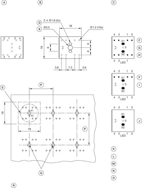 A = Terminals (rear side)
B = Drilling plan (component side)
C = non-metallic
D = Cu-Pad
E = Occupancy plan (component side)
F = 1. Switch
G = Switching element 2 Normaly close + 2 Normaly open, Part No. 71-672.026
H = 2. Switches
I = Switching element 1 Normaly close + 1 Normaly open, Part No. 71-671.026
J = Illumination element, Part No. 71-670.026
K = X1 Lamp cathode (-)
L = X2 Lamp anode (+)
M = 1-2 Contact normally closed
N = 3-4 Contact normally open
O = 5 Hole for interlocking pin
P = Front dimension min.
Q = Position interlocking pin
R = Note:
Pitch of the print circuit board hole Ø3.5 must agree with the mounting holes on the front plate
S = Slot in actuator
Download files
0 in stock Loading ...
Add to Cart